Latest Advancements in GNSS Receiver Technology: Inside the Trimble ST30
An in-depth look at the Trimble ST30 smart target, covering how it brings tilt compensation to total station measurements for the first time, alongside automatic rod height, industry-leading optical tracking and integrated GNSS
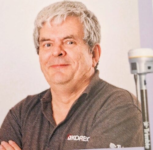
Philip is KOREC's GNSS specialist, bringing decades of positioning and survey expertise, from his time in the Royal Engineers to supporting and training our customers today. He's a trusted voice on emerging GNSS challenges, from signal spoofing to solar interference.
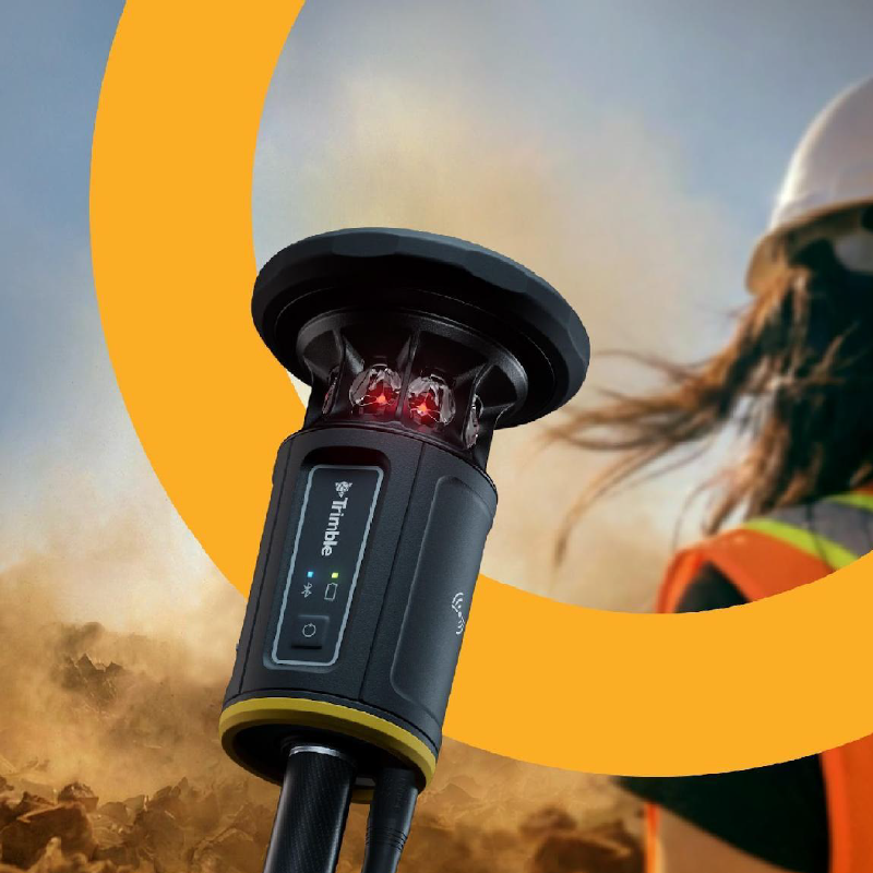
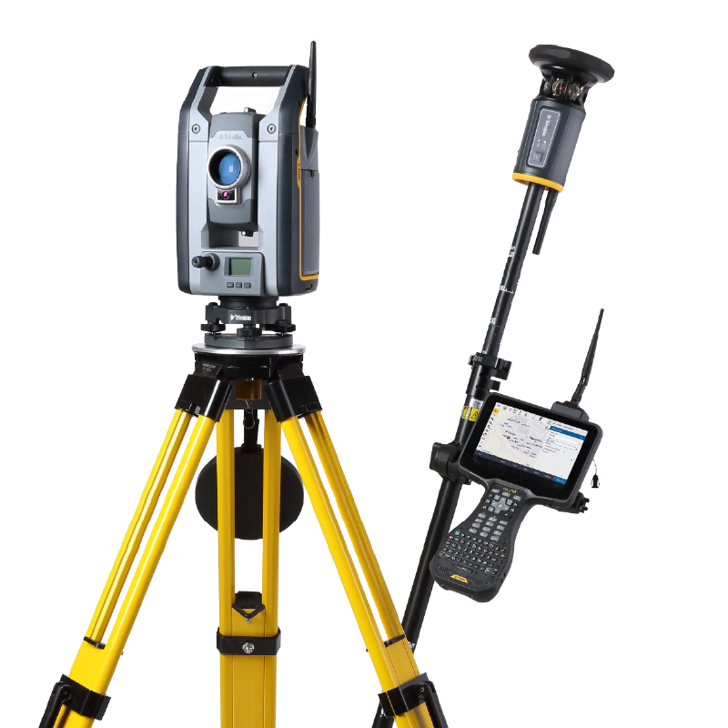
GNSS receiver technology has moved on considerably from the days of carefully levelling a pole before every shot. The clearest example of that shift right now is the Trimble ST30, a smart target that combines optical tilt compensation, GNSS positioning, automatic rod height and best-in-class tracking into a single, versatile system.
This guide looks at what makes the Trimble ST30 significant, starting with tilt compensation, its standout capability, before covering the rest of the technology working behind the scenes.
Why This Matters for GNSS Receiver Technology
Levelling the pole before every observation has always been one of the small, repeated frictions of fieldwork. On flat, open ground it costs a few seconds per shot. At building corners, inverts, overhead structures or anywhere the rod cannot sit perfectly vertical, it costs considerably more, and often forces a surveyor to use offsets or COGO calculations to reach the point at all.
GNSS rovers solved this problem for GNSS measurements some years ago with IMU-based tilt compensation (see our guide on IMU-based tilt compensation). What has not existed until now is the equivalent for total station measurements. The Trimble ST30 closes that gap.
Optical and GNSS Tilt Compensation
The Trimble ST30 saves time and accelerates fieldwork by extending Trimble TIP tilt compensation to total station measurements, alongside the GNSS tilt compensation already familiar from Trimble’s GNSS receivers. It is the capability the Trimble ST30 is built around.
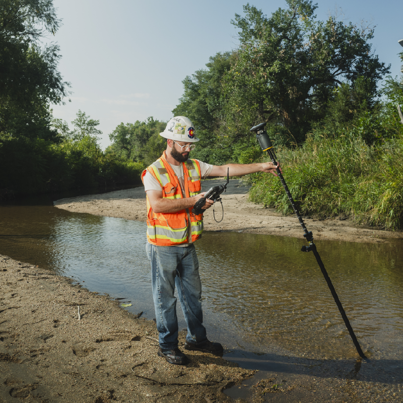
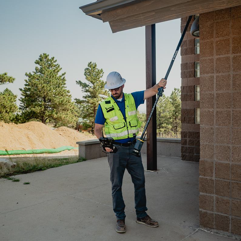
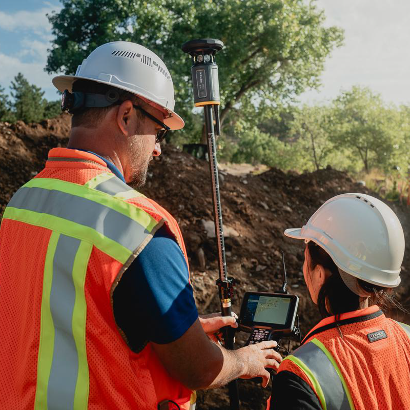
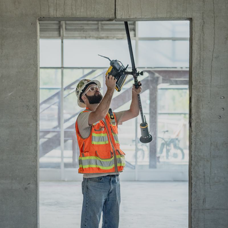
There is no need to carefully level the rod for every shot, which dramatically speeds up topographic surveys and stakeout tasks. It also makes previously inaccessible or hard-to-reach points, such as building corners, inverts or overhead structures, far easier to measure, minimising extra steps and removing the need for complex COGO offsets.
Extending tilt compensation to total station measurements is a harder problem than it sounds. In a GNSS rover, all the sensors, the antenna and the IMU, sit in the same housing, so their outputs are inherently synchronised. With a total station setup, the tilt sensor is in the target while the angle and distance measurements come from the total station, potentially hundreds of metres away. Fusing that data accurately requires timestamping to better than one millisecond.
Trimble’s solution is a purpose-built Bluetooth radio system, referred to as BLR (Bluetooth Long-range Robotic), which achieves time synchronisation to under 5 microseconds on average across a working range of up to 1,000 metres. A dedicated data channel carries horizontal angle, vertical angle and slope distance from the total station to the controller, alongside a timing beacon sent directly to the Trimble ST30. The Trimble ST30’s onboard ProPoint engine then fuses this with its own IMU data to compute a tilt-corrected position, drawing on the same Trimble Inertial Platform (TIP) technology proven in the R980 and R780 GNSS receivers.
The published accuracy figures for TIP-compensated optical surveying illustrate how tightly this is controlled: at a rod height of 1.6 m, horizontal error is TS + 2 mm + 0.3 mm per degree of tilt, and vertical error is TS + 1 mm + 0.1 mm per degree of tilt. Tilt compensation is supported through a working range of up to ±40° from vertical. Full specifications are available on the product page.
What’s Inside the Trimble ST30
Externally, the Trimble ST30 looks like a conventional 360° prism on a telescoping rod. Internally, it is considerably more sophisticated. Key components include:
GNSS antenna and receiver, with an integrated IMU (inertial measurement unit), providing satellite positioning and tilt sensing in the same housing.
Eight corner cube prisms with an apex cut, arranged behind a single ring of infrared LEDs (785 nm), rather than the dual LED ring used on earlier targets such as the MT1000.
An EDM (electronic distance meter), used specifically for automatic rod height measurement rather than target tracking.
A 35 Wh Trimble Li-35 battery, powering the electronics, LEDs and radio.
A main board with an integrated radio module, handling communication with the total station and controller.
This hardware supports the features Trimble positions as the core of the Trimble ST30: tilt compensation for both optical and GNSS workflows, integrated GNSS, industry-leading tracking, and automatic rod height.
Automatic Rod Height
Incorrect rod height entry is a well-known source of field blunders, and one that is expensive to catch after the fact. The Trimble ST30 addresses this with a continuous, automatic height measurement rather than a manually entered value.
A small EDM engine inside the target (Trimble’s “mini-brontes”) sends a laser beam down the hollow centre of the rod to a reflector prism fixed at the base. The beam widens as it travels, from roughly 22.8 mm to 87 mm in diameter by the time it reaches the bottom of the rod, and the return signal is used to calculate the exact rod height in real time, updated at 1 Hz and synchronised directly with the field software. The measured accuracy is ±0.6 mm RMS.
A neatly engineered side effect of this design is water detection. If water pools inside the rod, it breaks the total internal reflection that the corner cube prism relies on, so the system returns a zero signal and flags the fault automatically rather than silently producing an incorrect height.
Industry-Leading Tracking
The optical block itself has also been redesigned. Earlier Trimble targets, such as the MT1000, used a dual LED ring for tracking, which degraded once the target was tilted. The Trimble ST30 instead uses a single ring of protected LEDs positioned behind the eight prisms, a layout validated through prototype testing (internally codenamed “Roubaix”) to keep the tracking signal balanced across the target regardless of rotation. This allows the Trimble ST30 to maintain accurate tracking through up to ±40° of tilt, considerably more than earlier designs, with the LEDs themselves protected behind the prisms and the whole unit further protected by a bumper.
Passive tracking range extends from 1.5 m to 500 m, and active tracking from 1.5 m to 600 m, with horizontal accuracy of under 2 mm RMS and vertical accuracy of under 1 mm RMS. GeoLock, which uses the Trimble ST30’s built-in GNSS and standard Trimble RTX corrections to automatically regain lock if line-of-sight is interrupted, is included out of the box at no extra subscription cost.
Integrated GNSS
The Trimble ST30 is built with full GNSS receiver hardware on board. GeoLock, covered above, already draws on this hardware today: it uses the built-in GNSS and standard Trimble RTX corrections to automatically regain lock if line-of-sight is interrupted, included as standard at no extra cost.
The Trimble ST30 will also support full GNSS rover capabilities*, letting it switch between optical and GNSS measurements within the same job file with no equipment change.
*GNSS rover capabilities releasing in 2027.
Built for the Field
Alongside the sensor technology, the Trimble ST30 is paired with a redesigned telescoping rod (1.55 m to 2.6 m, supporting the automatic height measurement), a carbon fibre body for reduced weight and bending, a fiberglass upper section for radio transparency, and a titanium tip rated as six times harder than standard alloy tips. The target itself is rated IP67 and is designed to survive a 2.6 m pole drop onto concrete, alongside MIL-STD-810H vibration and shock testing.
How the Trimble ST30 Fits Into Your Existing Setup
The Trimble ST30 is designed to slot into an existing Trimble ecosystem rather than requiring a completely new one. It is compatible with:
Total stations: Trimble RTS and SPS series, and select S series instruments (all S7, S9 and S9 HP models, plus S5 models with the Active Tracking option) for active tracking, provided the instrument has a DR+ EDM and is fitted with a BLR radio for tilt-compensated optical measurements. A radio firmware update is required on the total station side to enable communication with the Trimble ST30.
Controllers: Trimble TSC5, TSC510, TSC7, TSC710, T10, T110, T7 and T70, as well as supported Android and iOS devices.
Radio module: the new Trimble Empower EM140, which uses the same antenna as its predecessor, the EM120, and adds support for the BLR-based optical tilt workflow.
Field software: Trimble Access 2026.20 or later, Trimble FieldLink 2026.2.0 or later, or Trimble Siteworks 2.0 or later.
Land surveying: tilt compensation removes the need for manual levelling at difficult features such as building corners and inverts, and active tracking with GeoLock reduces time lost to line-of-sight issues in obstructed or wooded areas.
Construction setting out: automatic rod height removes a common and costly cause of rework, and tilt compensation allows measurement around obstructions such as rebar or plant without repositioning the instrument. See our guide on the benefits of using GPS in construction setting out for more on this theme.
Infrastructure projects: tilt compensation supports safer measurement near live traffic or rail corridors, without needing to stand directly on the point.
Frequently Asked Questions
What is the Trimble ST30?
The Trimble ST30 is a smart target that combines optical tilt compensation, GNSS positioning and best-in-class optical tracking in a single pole-mounted device. Full details are available on the Trimble ST30 product page.
What is the main advantage of the Trimble ST30?
Its headline feature is tilt compensation for optical surveying: the pole no longer needs to be levelled before every shot, which speeds up topographic surveys and stakeout work and makes previously awkward points, such as building corners, inverts and overhead structures, much easier to measure.
Can the Trimble ST30 be used as a standalone GNSS rover?
The hardware supports it, and GeoLock already uses the built-in GNSS and standard RTX corrections today at no extra cost. Full GNSS rover capabilities will be available as a separate subscription option.
Does the Trimble ST30 need a subscription to work?
No subscription is needed for the features available today, including tilt-compensated optical surveying, automatic rod height and GeoLock-assisted tracking, which all come standard. A subscription will only be needed for GNSS rover capabilities.
What total stations work with the Trimble ST30?
Active tracking is supported on Trimble RTS series, Trimble SPS series, and select S series total stations (S7, S9 and S9 HP, plus S5 with the Active Tracking option). Tilt-compensated optical measurements additionally require a DR+ EDM and a BLR-compatible radio, which may need a firmware update on older instruments.
How accurate is the automatic rod height feature?
The Trimble ST30’s automatic rod height measurement is accurate to ±0.6 mm RMS, updated at 1 Hz, and is synchronised directly with the field software.
How much tilt can the Trimble ST30 compensate for?
The Trimble ST30 supports tilt compensation, for optical measurements today and for GNSS measurements once GNSS rover capabilities arrive, through a working range of up to ±40° from vertical.
Explore More GNSS Guides
This article is part of KOREC’s ongoing series on GNSS technology. You may also find these guides useful:
KOREC can advise you on the right GNSS system for your project. Speak to our friendly experts today to get the right technology to solve your business challenges.