Integrating GNSS with Total Stations and Laser Scanners
Find out how to combine GNSS receivers, total stations, and laser scanners in a single survey workflow, covering coordinate control, field sequencing, and practical quality checks at each stage.
Philip is KOREC's GNSS specialist, bringing decades of positioning and survey expertise, from his time in the Royal Engineers to supporting and training our customers today. He's a trusted voice on emerging GNSS challenges, from signal spoofing to solar interference.
No single instrument does everything well. GNSS rovers cover open ground quickly, and modern receivers have significantly improved performance in partially obstructed conditions, but they still can’t match a total station for precision close to buildings or under dense canopy. Total stations provide precise line-of-sight measurement but need established control and a clear path to the prism. Laser scanners capture surface geometry at scale, and the output is already survey-grade; what it lacks without georeferencing is a position within the project’s coordinate system. The most productive and capable survey workflows combine all three, using each instrument where it performs best and connecting them through a shared coordinate framework.
This guide covers the practical decisions involved in building that integrated workflow. For an introduction to GNSS receiver setup and positioning modes, see our GNSS receiver setup guide. For guidance on tilt compensation in GNSS rovers, see IMU-based tilt compensation explained. Alternatively for guidance on the difference between GNSS and GPS technology see our guide GNSS vs GPS: What are the difference?
Why Integrate Multiple Instruments?
A survey team using only GNSS leaves gaps where satellite signals are blocked. A team using only a total station faces slow coverage on large open sites and needs control to work from. A team using only a laser scanner produces data that is only as accurate as its georeferencing, and without it the data sits in a local reference system rather than the project’s coordinate system. Integration removes each of these constraints by allocating work to the instrument best suited to it.
The practical benefits are faster field time, better coverage, and a more complete dataset. A GNSS rover and a total station working in the same session, whether recording directly in the same coordinate system or in separate systems merged during post-processing, can cover a mixed urban and open site in the time it would take either instrument alone to cover just one part of it. Adding a laser scanner to that workflow captures the structural and surface detail that neither the rover nor the total station would pick up point by point.
The Foundation: A Shared Coordinate System
Integration across multiple instruments only works if all data ends up in the same coordinate system, whether it’s collected that way directly or merged into alignment during post-processing. This sounds straightforward but is one of the most common sources of error on multi-instrument projects, particularly when GNSS and total station data are combined.
Establishing Control with GNSS
The most efficient way to establish control for a multi-instrument survey is to use a GNSS rover to observe a network of control points across the site before any other instrument is deployed. The Trimble R980 and Trimble R580 both deliver 8 mm + 1 ppm horizontal RTK accuracy using Trimble VRS Now network corrections, which is sufficient for control that will underpin total station and scanner work on the vast majority of survey projects.
Control points should be placed at stable, unobstructed locations with good sky visibility, distributed across the site with at least one in each area where the total station will need to set up. Mark each point clearly and record its position as the coordinate, not as a staked point that requires re-observation.
Coordinate System and Datum Consistency
Before any observations are made, confirm that the GNSS receiver is configured to output coordinates in the correct coordinate system for the project. In the UK this is typically OSGB36 National Grid with ODN heights, accessed through the OSTN15 transformation model in Trimble Access. Irish projects typically use ITM with Malin Head heights. The total station and scanner must be set up and registered in the same system.
Coordinate system mismatches between GNSS and total station data are the most common source of systematic error in integrated surveys. A receiver configured to output ETRS89 coordinates while the total station is set up on National Grid control will produce data that appears consistent internally but does not overlay correctly. Confirm the coordinate system at the start of every project and check it again if results look unexpectedly inconsistent.
Local vs Grid Coordinates
Some projects use a local site coordinate system rather than a national grid, particularly in construction where the design model is referenced to site-specific axes. In these cases, GNSS control must be transformed into the local system before it is used to set up the total station. Trimble Access handles this through a site calibration procedure, which derives the transformation parameters, including horizontal and vertical shifts, rotation, and scale factor, from observations to a minimum of three known points in both the local and GNSS reference frames. A well-distributed calibration with four or more points and verified residuals provides a robust local coordinate framework.
Integrating GNSS with Total Stations
Setting Up the Total Station on GNSS Control
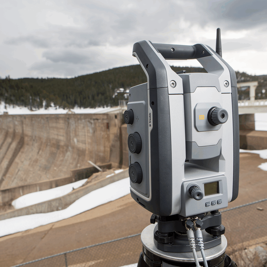
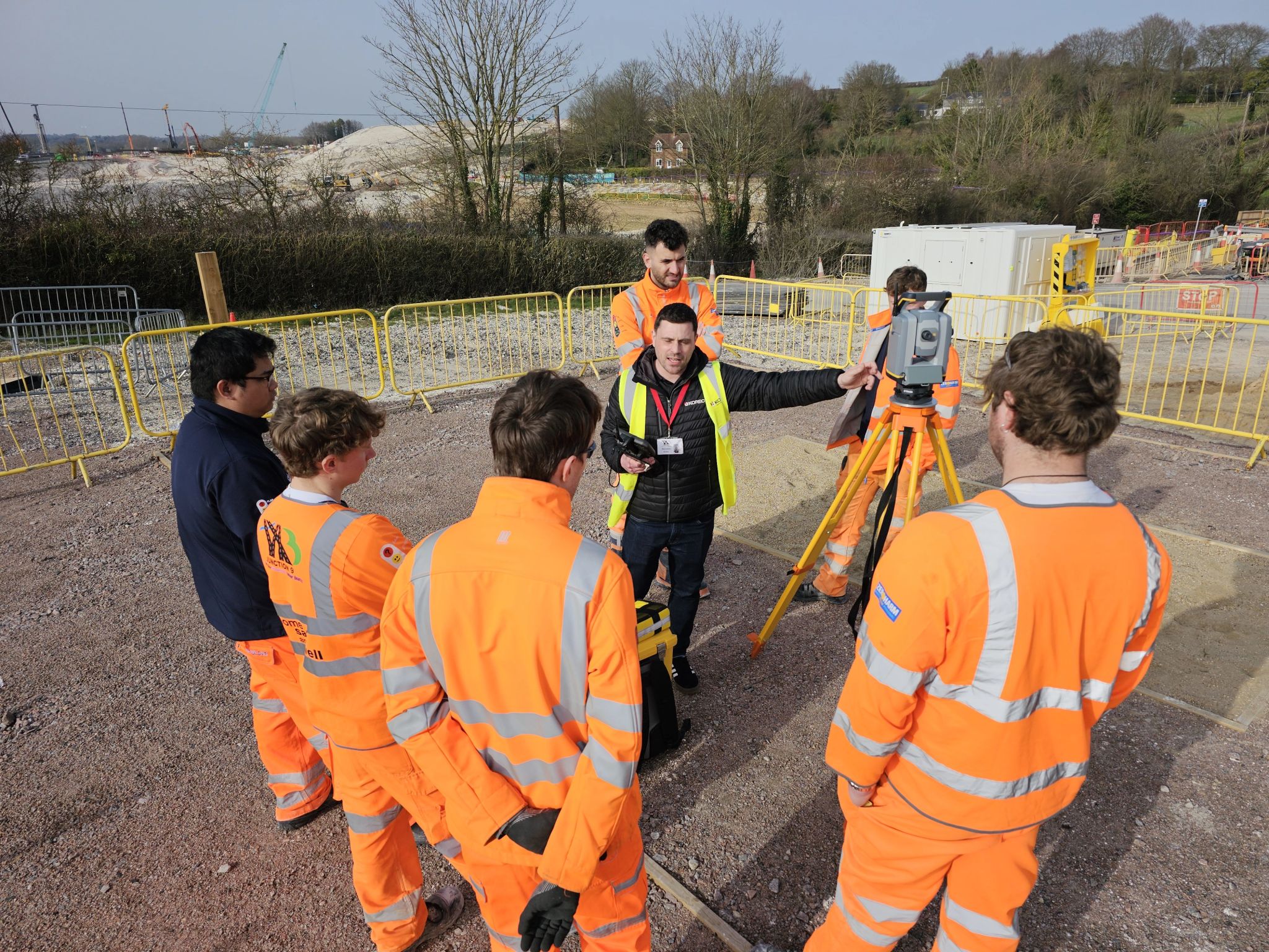
A robotic total station, such as the Trimble S Series, is typically set up over a known control point and oriented by observing one or more additional control points, establishing its position and orientation in the project coordinate system. When the control network has been established by GNSS, the total station setup procedure is the connection between the GNSS-derived control and the total station’s measurements.
Resection is the alternative approach: the total station is set up at a convenient but unknown position and oriented by observing three or more known control points. This is more flexible than occupying a control point directly and produces an accurate station position provided the control points are well-distributed and the observations are carefully made. In Trimble Access, both approaches use the same coordinate system, and observations from the total station are stored in the same project file as GNSS observations.
Hybrid Positioning on Site
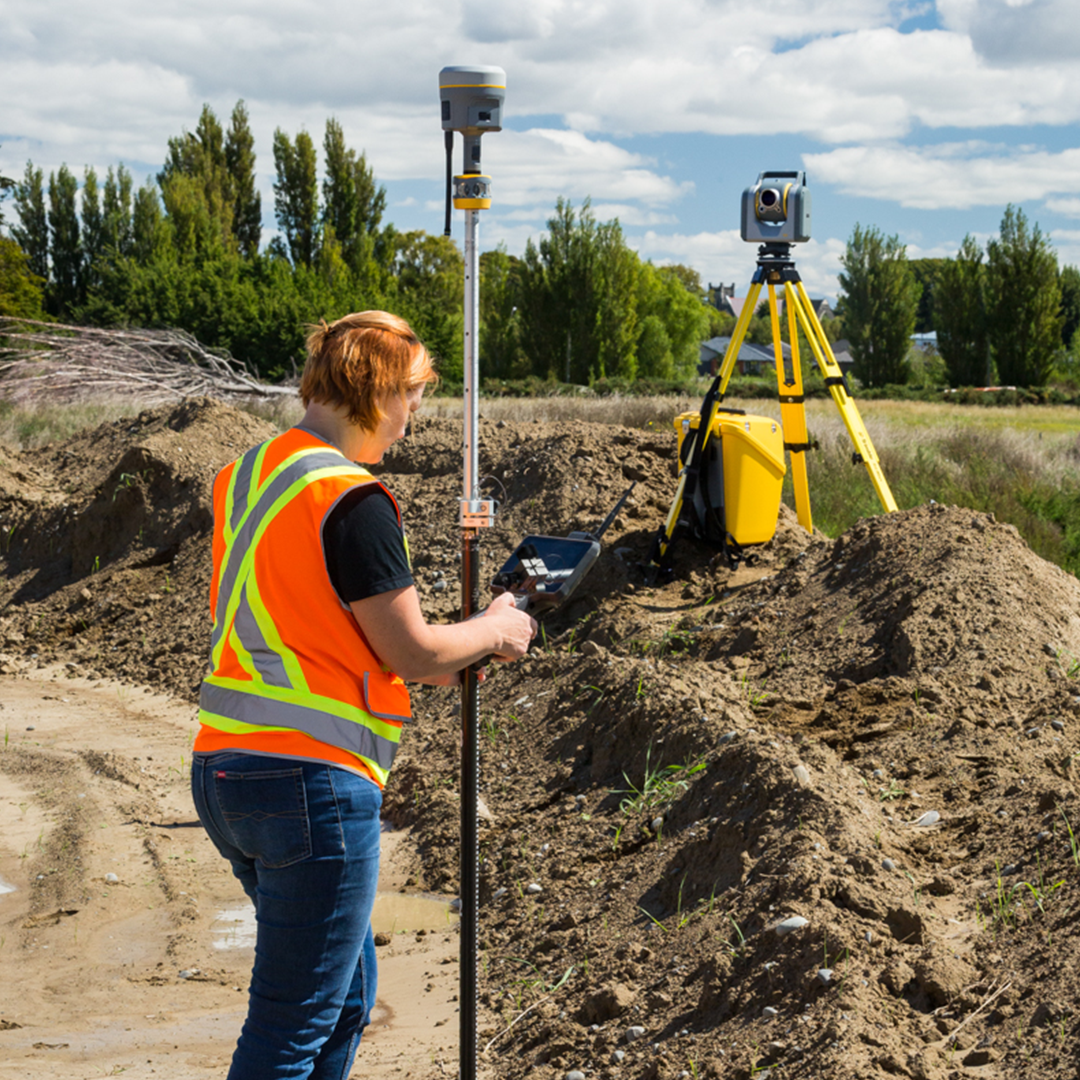
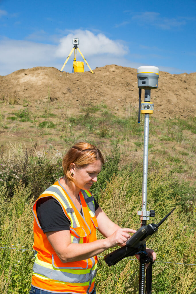
On a mixed site, GNSS and total station work can proceed simultaneously or sequentially depending on team size. A single operator with a GNSS rover and a robotic total station can use the rover to cover the open areas while the total station, running autonomously, measures prisms in the obstructed sections. Both data streams are collected in Trimble Access and export together into Trimble Business Center without any conversion step.
The value of this hybrid approach is most apparent on sites where neither instrument alone would produce a complete dataset. A river corridor survey with open floodplain, dense vegetation, and masonry bridges is a typical example: GNSS covers the floodplain, the total station covers the bridge structure and the areas beneath the tree canopy, and both outputs combine into a single dataset.
Check Measurements and Quality Control
Whenever total station observations depend on GNSS-established control, check measurements are essential. After setting up the total station on control, observe at least one additional control point that was not used in the setup or resection, and confirm that the observed coordinate matches the GNSS-established coordinate within the project accuracy tolerance. Record this check in the field notes. If the check fails, investigate before proceeding with any further observations; an incorrect or unapplied scale factor is one of the more common causes of a check point failure that otherwise looks like a measurement error.
Integrating Laser Scanners with GNSS and Total Stations
How Laser Scanners Are Georeferenced
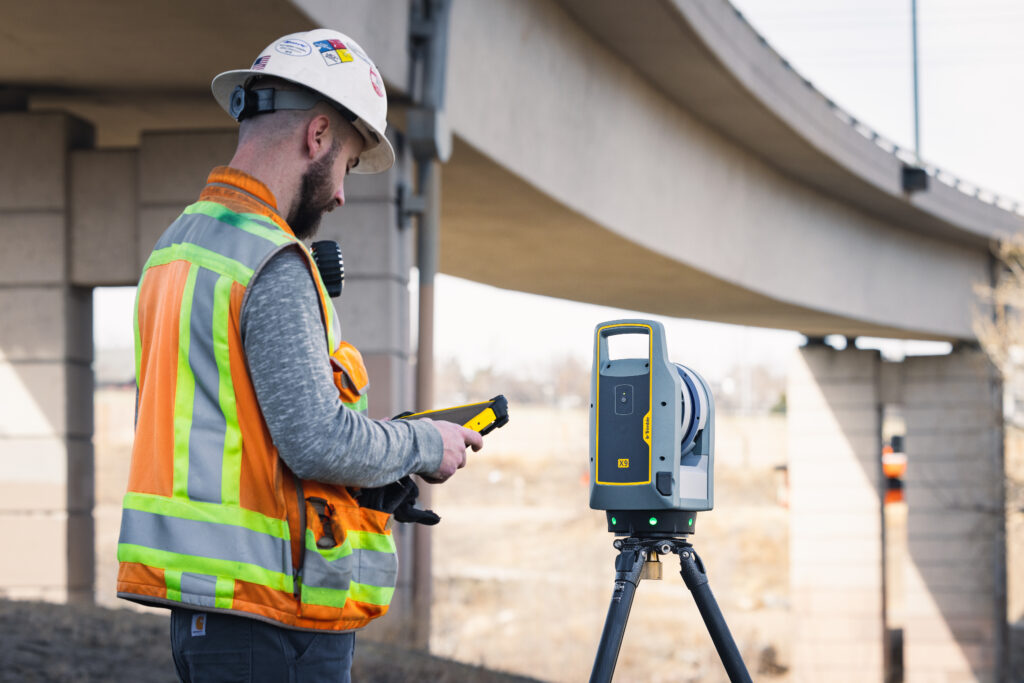
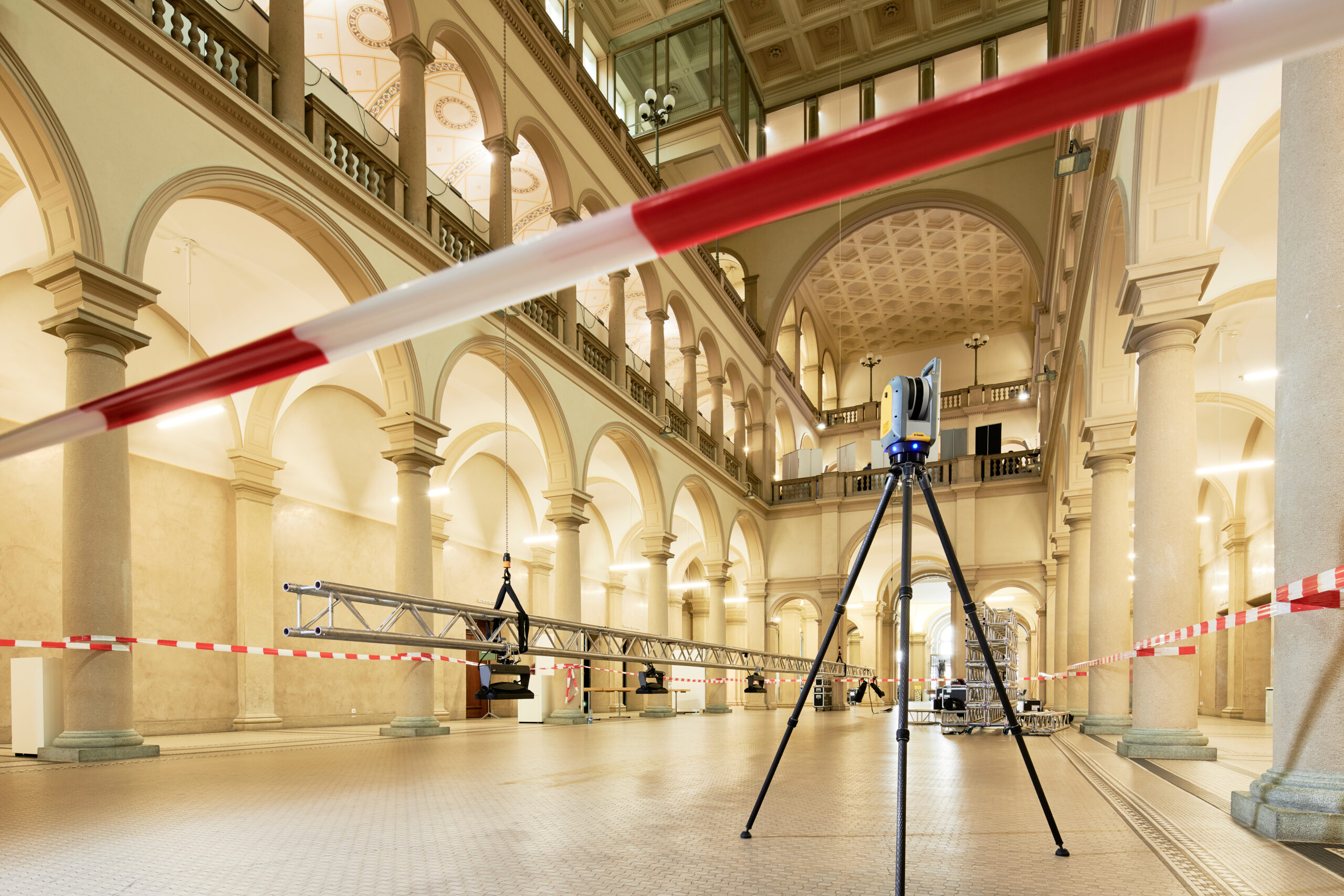
A laser scanner, such as the Trimble X9, Trimble X7, or Trimble X12, captures its data in the scanner’s own local coordinate frame. Georeferencing is the process of transforming that data into the project coordinate system, which is what gives the point cloud its survey-grade spatial accuracy. Without accurate georeferencing, a scan is a geometrically correct but spatially unlocated dataset.
There are two primary approaches to georeferencing scanner data: target-based registration and cloud-to-cloud registration. In most professional survey applications, target-based registration is the more reliable method and the one that connects most directly to the GNSS and total station control framework established earlier in the workflow.
Using Surveyed Targets for Scanner Georeferencing
The most straightforward connection between scanner data and the project coordinate system is to place surveyed targets within the scanner’s field of view and measure those targets with the total station or GNSS rover before or after scanning. The targets are then identified in the point cloud during registration, and the known coordinates of each target are used to georeference the scan. Trimble Perspective extends this further, allowing any point identifiable in the scan data to be georeferenced and then coordinated directly using a total station or GNSS rover, rather than relying solely on dedicated targets.
This approach works because the total station and GNSS data are already in the project coordinate system. The targets act as the bridge between that coordinate system and the scanner data. For this to work accurately, the targets must be stable between the GNSS or total station observation and the scan, clearly identifiable in the point cloud, and distributed so that the scanner has a minimum of three, preferably four or more, visible from each scan position. The scanner does not scale its own data to fit the control; instead, the registration process reports how well the scan matches the surveyed target coordinates, giving a direct check between the scanner data and the control.
Scanner Position from GNSS or Total Station
The Trimble SX12 scanning total station takes a different approach, combining robotic total station and scanning capability in a single instrument. Because it functions as a total station, it can be set up directly over a known control point, oriented in the project coordinate system, and used to scan from a georeferenced position. This eliminates the separate target survey step entirely for single-position scans and significantly simplifies multi-position workflows.
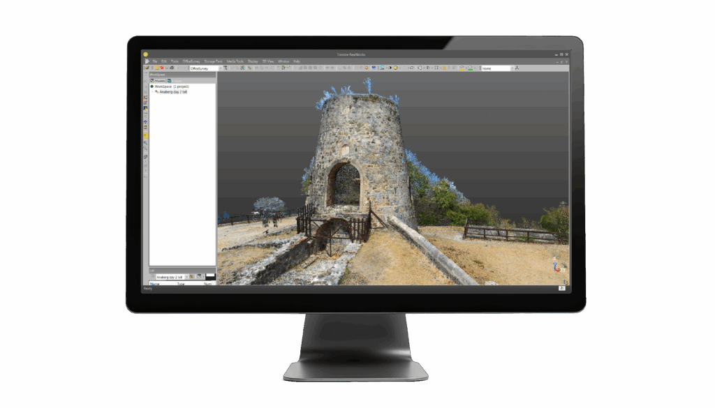
For standalone terrestrial scanners, Trimble RealWorks is the standard processing platform, handling target detection, scan registration, and point cloud analysis. Scans registered against surveyed targets and checked against independent points produce a georeferenced point cloud whose accuracy is determined by the quality of the target survey, not by the scanner’s internal geometry alone.
Cloud-to-Cloud Registration
Cloud-to-cloud registration aligns overlapping scans by finding the best geometric match between common surfaces. It does not require surveyed targets in each scan but depends on sufficient geometric overlap between adjacent positions. On its own, cloud-to-cloud registration accumulates positional drift across a long sequence of scans and produces a dataset that is internally consistent but not necessarily in the project coordinate system. The Trimble X7 and X9 reduce this risk in practice by self-registering scans in real time as the job progresses, giving the operator an immediate check on alignment quality rather than waiting until office processing. For survey-grade outputs, cloud-to-cloud is still most useful as a supplement to target-based registration, refining the alignment between scans rather than establishing the coordinate framework on its own.
Field Sequencing for Multi-Instrument Surveys
The order in which instruments are deployed has a direct effect on efficiency. A well-planned sequence minimises revisits and ensures that each instrument has the information it needs before work begins.
Establish GNSS control first, observing a distributed network of points in the project coordinate system before any other instrument is deployed
Set up the total station on the GNSS control and confirm the setup with a check observation before recording any survey data
Place scanner targets in positions visible from planned scanner positions, then survey those targets with the total station or GNSS rover
Scan from each planned position, confirming overlap with adjacent scans before moving
Carry out GNSS rover observations in open areas, collecting the same feature codes used by the total station for seamless data merge
Before leaving site, confirm that check point residuals and scanner registration quality are within tolerance
The key discipline in multi-instrument sequencing is not starting the next instrument before the previous step has been confirmed. A scanner set up before targets have been surveyed, or a total station set up before the setup check has been verified, creates downstream problems that are expensive to resolve without a return visit.
Software: Connecting the Instruments
Trimble Access in the Field
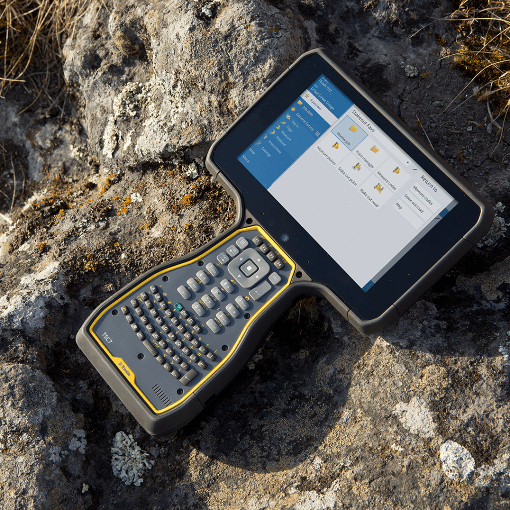
Trimble Access is the field software environment for both GNSS rovers and Trimble S Series total stations, running on the TSC510 and TSC710 data controllers. Both instrument types connect to the same project file, share feature code libraries and coordinate systems, and export data together into Trimble Business Center. The Trimble Access module structure means that GNSS survey, total station survey, and scanning workflows all operate within the same software framework, reducing the learning overhead for teams moving between instrument types on site.
Trimble Business Center in the Office
Trimble Business Center is the office processing environment that brings all instrument data together. GNSS observations, total station data, and scanner point clouds registered in Trimble RealWorks can all be imported into a single Trimble Business Center project, where they are held in a common coordinate system and can be combined for deliverable production. Quality checks, coordinate transformations, and deliverable exports are all managed from this single environment.
For teams working in a BIM or construction management environment, Trimble Connect provides the collaboration layer above Trimble Business Center, allowing combined datasets to be shared with project stakeholders without specialist software on their side.
Trimble Perspective in the Field
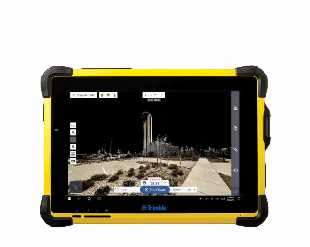
Trimble Perspective sits alongside Trimble Access as field software, purpose-built for in-field scanner control and registration when working with the Trimble X9, X12, or X7 laser scanning systems. It gives the operator full control over scans on site, with in-field registration and georeferencing that lets the team verify the data is correctly registered before leaving the jobsite, rather than discovering a problem back in the office.
Common Integration Challenges and Solutions
Coordinate System Mismatches
The most frequent cause of data that will not overlay correctly is a coordinate system mismatch between the GNSS data and the total station or scanner data. Check the coordinate system in the GNSS receiver settings, the Trimble Access project settings, and the Trimble Business Center import settings at the start of every project. If data from two instruments does not align, the coordinate system configuration is almost always the first place to look.
Height Inconsistencies
GNSS heights are ellipsoidal unless a geoid model is applied. Total station heights are related to the benchmark datum used in the survey. If the GNSS configuration does not include the correct geoid model for the project, GNSS-derived heights will be inconsistent with total station and levelling data. In the UK, the OSGB36 transformation in Trimble Access applies the OSTN15 transformation and the OSGM15 geoid model simultaneously, giving National Grid coordinates with ODN heights. Confirm this is configured before making any height-critical observations.
Scanner Registration Residuals
High residuals in scanner registration indicate that the targets used to georeference the scan are not providing a consistent spatial fix. Common causes include targets that moved between being surveyed and being scanned, targets that are too few or poorly distributed, and targets identified incorrectly in the point cloud. Always use a minimum of four targets per scan position, confirm that each is stable, and check the registration residuals before moving to the next scanner position.
GNSS Systems and Integration Support from KOREC
KOREC supplies the full range of Trimble GNSS systems, total stations, and laser scanners alongside Trimble Access, Trimble Business Center, and Trimble RealWorks as the integrated software environment. As the authorised Trimble dealer for the UK and Ireland, KOREC provides in-person training on multi-instrument workflows, UK and Ireland-based technical support, and KOREC Care Packages for ongoing servicing and calibration. To discuss your integration requirements, contact our team via the surveying or mapping and GIS industry pages.
Frequently Asked Questions
Can GNSS and total station data be combined in Trimble Access?
Yes. Trimble Access manages GNSS and total station observations in the same project file, using a single coordinate system. Both instrument types store data in the same format and export together into Trimble Business Center without any conversion or merging step required. Trimble Access also supports Integrated Surveying, which combines both methods within a single measurement session, letting the operator switch between GNSS and total station observations at the push of a button.
How many targets do I need to georeference a laser scan?
A minimum of three targets is required to georeference a scan mathematically, but four or more are strongly recommended in practice. With three targets, there is no redundancy: a single target error or misidentification will corrupt the registration without providing any indication that something is wrong. Four or more targets provide the redundancy needed to detect and isolate any inconsistency.
What is the most common cause of data misalignment in multi-instrument surveys?
Coordinate system misconfiguration is the most common cause. This typically occurs when the GNSS receiver outputs coordinates in one system, such as ETRS89, while the total station is set up on control that was recorded in another, such as National Grid. The data appears internally consistent but does not align when combined. Confirming the coordinate system configuration at the start of every project, in both the receiver settings and the Trimble Access project settings, prevents this in most cases.
Does KOREC provide training on integrated multi-instrument workflows?
KOREC provides structured in-person training covering GNSS, total station, and laser scanner workflows individually and in combination. Training is available at the point of equipment purchase or at any stage during the instrument’s working life. For more detail on training options, see the KOREC training page or contact our team directly.
Learn how to integrate GNNS systems with Total Stations and Laser Scanners
KOREC can advise you on how to integrate GNSS systems with Total Stations and Laser Scanners. Speak to our friendly experts today to get the right technology to solve your project challenges.
How 3D Laser Scanners Are Used at Crime and Collision Scenes
Find out how 3D laser scanners capture complete crime and collision scenes in minutes, why speed matters for scene clearance, and how point cloud data supports evidence analysis and court...
What Equipment Is Used in Forensic Scene Documentation?
Discover the geospatial equipment used at crime and collision scenes, from 3D laser scanners and total stations through to GNSS, and how each tool contributes to accurate, court-ready documentation.
If a project requires refurbishment, redevelopment, restoration or extension of an existing property, it is likely that a measured survey will be required. Here we dig deeper into why, what...