IMU-Based Tilt Compensation Explained
This article explains how IMU-based tilt compensation works, what it means for day-to-day GNSS surveying, and how it performs on the Trimble R980.




This article explains how IMU-based tilt compensation works, what it means for day-to-day GNSS surveying, and how it performs on the Trimble R980.
For decades, accurate GNSS field measurement depended on a precisely levelled pole. Every observation required the bubble to be centred before the point could be recorded. On flat, open ground that added a few seconds per shot. On slopes, at building corners, along roadsides, or at any awkward feature, it could add considerably more, and introduced a persistent temptation to record a point that was not quite level. IMU-based tilt compensation removes that requirement entirely. Receivers such as the Trimble R980, available from KOREC, continuously track the orientation of the receiver and apply a real-time correction so that survey-grade positions can be recorded with the pole tilted, supporting a tilt range of up to 40 degrees off-vertical with only a small, well-defined increase in error as tilt increases.
This article assumes some familiarity with GNSS positioning. For an introduction to the technology and how it differs from GPS, see our guide on the difference between GNSS and GPS.
A GNSS receiver measures the position of its antenna. The surveyor needs the position of a point on the ground. The pole connects the two, and the geometry only works cleanly when the pole is vertical. When it leans, the antenna is displaced horizontally from the point being measured, and that displacement grows with both the tilt angle and the pole length. A 2-metre pole tilted at just 10 degrees shifts the antenna more than 34 centimetres from directly above the pole tip. At 20 degrees, the offset exceeds 68 centimetres. For any application requiring centimetre-level accuracy, even small undetected tilt is significant.
Tilt errors are also systematic rather than random. The direction of lean isn’t fixed: a surveyor may lean the pole differently depending on the obstruction at each feature. But for a given feature type, reaching past the same kind of obstacle in a similar way each time, the lean direction tends to be consistent. Every observation of that feature type then carries a similar directional bias. That bias persists in the processed dataset in a way that random measurement noise does not, and it tends to affect exactly the features where accurate measurement matters most: corners, edges, boundaries, and channel inverts.
An inertial measurement unit combines accelerometers, which detect linear forces, and gyroscopes, which detect rotational movement, to continuously determine the orientation of the receiver in three dimensions. When the pole tilts, the IMU detects the direction and magnitude of that tilt in real time. The receiver uses this information, together with the known pole length, to calculate where the pole tip actually is relative to the antenna, and applies a correction to the measured GNSS position before it is stored. The operator sees a corrected pole-tip coordinate, not the raw antenna position.
A key advantage of inertial compensation over older magnetic-based tilt systems is immunity to magnetic interference. Vehicles, heavy plant, steel reinforcement, and ferrous fencing all distort the local magnetic field and can cause magnetic tilt systems to fail silently. An IMU operates on physical principles alone and is unaffected by any of these sources of interference, making it reliable on construction sites, road corridors, and urban environments where magnetic-based systems are least dependable. It also has no moving parts, so there is no mechanical wear and tear to affect long-term reliability.
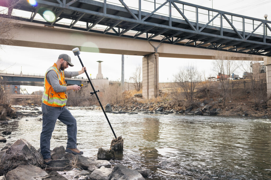
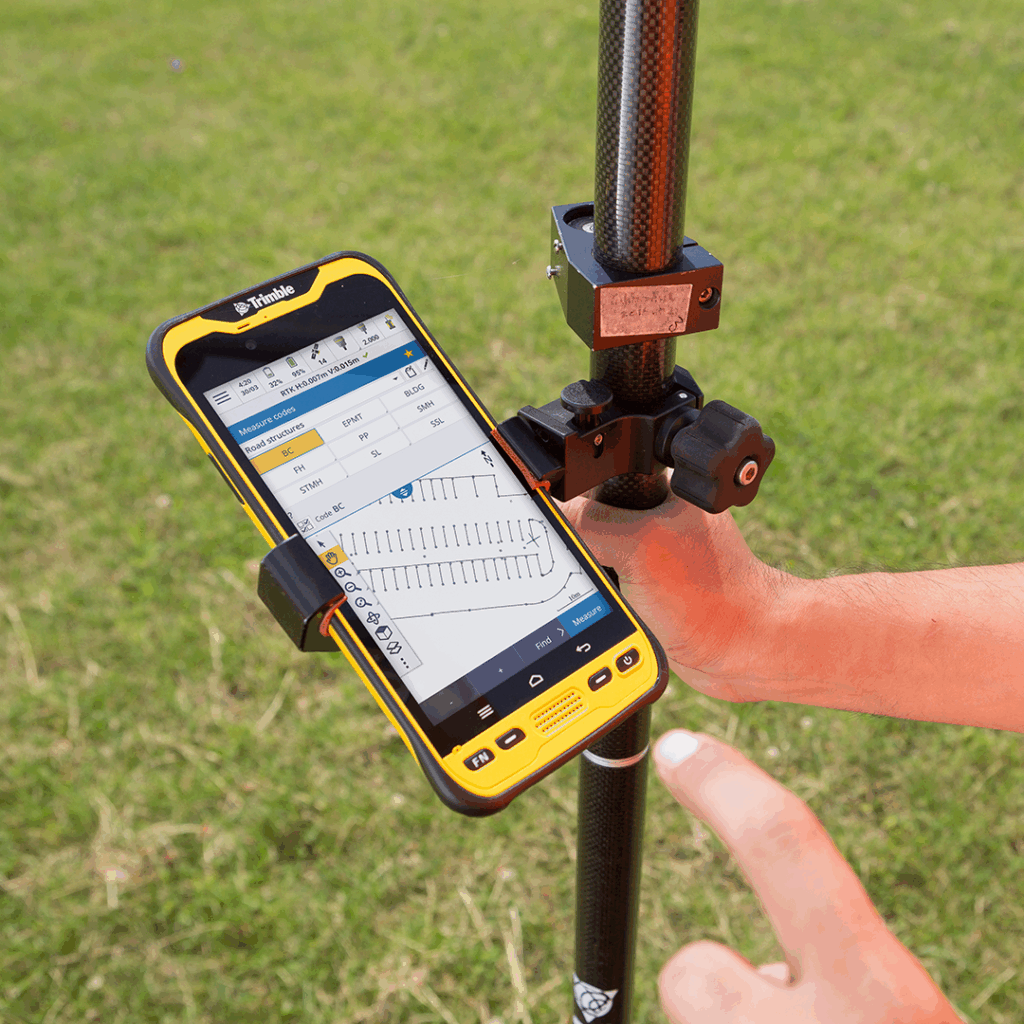
The Trimble R980 supports tilt-compensated measurement at angles of up to 40 degrees from vertical using Trimble’s Inertial Platform (TIP) technology, covering the full range of practical field situations. Within that range, the corrected position accuracy matches the receiver’s full RTK specification: 8 mm + 1 ppm horizontal and 15 mm + 1 ppm vertical. Tilt compensation is transparent to the measurement workflow: compensated observations are georeferenced and exported in exactly the same way as conventionally levelled ones, with no additional post-processing step required. Trimble Access handles both in the same workflow without distinction.
Before tilt compensation can be used, the IMU must be aligned to the GNSS reference frame. In practice this is achieved simply by walking normally with the pole, or moving it through a few natural positions: no dedicated routine is needed. Once aligned, the system maintains its orientation continuously and will realign itself automatically in good RTK conditions if alignment is lost due to a period of inactivity.
The R980 supports sensor calibration routines within Trimble Access. A pole bias adjustment should be performed whenever the receiver is moved to a different pole or quick-release adapter, to account for any offset between the pole axis and the IMU reference point. An electronic bubble calibration corrects the digital bubble display if it appears misaligned with the physical vial. An IMU bias calibration is available but should only be performed when the software specifically prompts it. These are infrequent maintenance tasks, not routine pre-survey procedures.
Tilt compensation has a measurable impact across most survey and construction applications, but it is most valuable at the precise points where levelling is hardest: building corners and wall bases, kerbstone edges and drain inverts, top-of-bank and bottom-of-bank on watercourses, fence lines and boundary features. These are also the locations where accurate measurement matters most for the integrity of the dataset. With tilt compensation enabled, each is measured in a single confident observation at full specification accuracy. Without it, the options are to accept a less precise result, spend additional time levelling in an awkward position, or take multiple shots and average them.
Roadside and corridor surveys benefit particularly from the safety dimension. Being able to take a measurement quickly without remaining stationary and focused on a bubble level in or near a live traffic lane materially reduces exposure to risk. The speed and safety arguments combine to make tilt compensation one of the highest-value features available on a modern GNSS rover.
The 40-degree working range covers most practical scenarios, but there are situations where the geometry falls outside it: measuring directly beneath an overhang, or capturing a deep, narrow invert, may require a conventionally levelled observation or an alternative technique. Tilt compensation also performs best when the underlying GNSS solution is strong. In environments where RTK fix quality is marginal, the combination of a weaker position and a tilt correction should be treated with additional caution, and independent check observations taken where the results are critical.
Antenna height accuracy remains essential. The tilt correction calculation relies entirely on the correct pole height being entered into the field software: an error here produces a systematic offset in every tilt-compensated observation. And while the IMU compensates for pole wobble automatically when the pole tip is stationary, the tip itself must not move during an active observation. Tilt compensation removes the levelling requirement; it does not remove the need for careful, considered fieldwork.
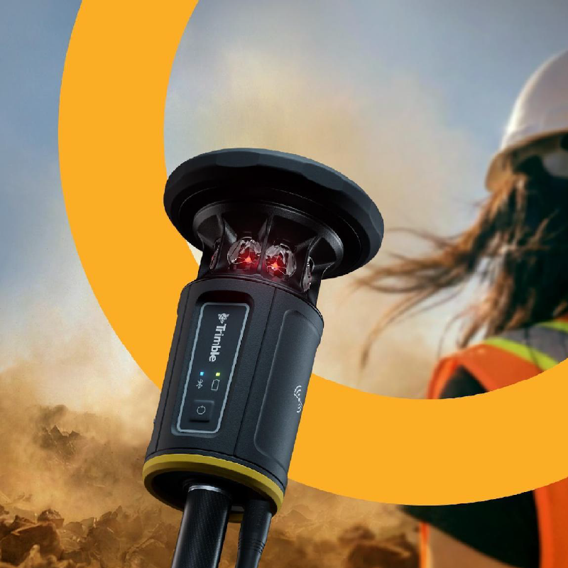
The Trimble R980 is KOREC’s flagship GNSS rover and the most capable implementation of IMU-based tilt compensation available in the range. Powered by Trimble’s ProPoint positioning engine and TIP tilt technology, it delivers 8 mm + 1 ppm horizontal and 15 mm + 1 ppm vertical RTK accuracy with tilt compensation active across the full 40-degree working range, alongside best-in-class performance in challenging environments including urban canyons and areas with partial canopy cover. With 672 channels, integrated 4G LTE, dual-band UHF radio, xFill correction outage protection, and an IP67-rated military-spec housing, it is built for professional surveying teams who need consistent, reliable results in all conditions. For teams requiring a capable mid-range option with TIP tilt compensation, the Trimble R980 and Trimble R780 also features TIP tilt technology alongside ProPoint positioning, making it a strong alternative for those requiring tilt compensation at a different price point.
It’s a technology that uses an inertial measurement unit, combining accelerometers and gyroscopes, to continuously track the orientation of a GNSS receiver. This allows the receiver to calculate and correct for pole tilt in real time, so survey-grade positions can be recorded without the pole needing to be perfectly level.
The Trimble R980 supports tilt-compensated measurement at angles of up to 40 degrees from vertical, with corrected position accuracy matching the receiver’s full RTK specification within that range.
Yes, significantly, if not compensated for. A 2-metre pole tilted just 10 degrees shifts the antenna more than 34 centimetres from directly above the pole tip, and at 20 degrees the offset exceeds 68 centimetres.
IMU-based systems operate on physical principles alone, using accelerometers and gyroscopes, so they’re unaffected by magnetic interference from vehicles, heavy plant, steel reinforcement, or ferrous fencing. Magnetic-based tilt systems can fail silently in these conditions, making IMU technology more reliable on construction sites and in urban environments.
The IMU needs to be aligned to the GNSS reference frame, which happens automatically by walking normally with the pole or moving it through a few natural positions, with no dedicated routine required. Separate calibration routines, such as pole bias adjustment or electronic bubble calibration, are infrequent maintenance tasks rather than steps needed before every survey.
Situations with geometry outside the 40-degree working range, such as measuring directly beneath an overhang or in a deep, narrow invert, may still require a conventionally levelled observation. Performance also depends on the strength of the underlying GNSS solution, and antenna height must still be entered correctly, as any error here produces a systematic offset in every tilt-compensated observation.
The Trimble R980 delivers 8 mm + 1 ppm horizontal and 15 mm + 1 ppm vertical RTK accuracy with tilt compensation active across its full 40-degree working range.
To discuss which system is right for your application, or to explore the full GNSS range available from KOREC, contact our team directly. You can also explore how GNSS technology supports workflows in surveying, mapping and GIS, and construction.
KOREC can advise you on which GNSS system offers the best solution to your project challenges. Speak to our friendly experts today.