UAV 3D Mapping: From Raw Data to Deliverables
Discover the full UAV 3D mapping workflow, from mission planning and data capture through to processing, georeferencing, and client-ready deliverables.


Discover the full UAV 3D mapping workflow, from mission planning and data capture through to processing, georeferencing, and client-ready deliverables.
UAV 3D mapping has transformed the way surveying and mapping professionals capture and present spatial data. Where traditional methods once required days of fieldwork, a well-planned drone mission can capture the same level of detail in a fraction of the time. But the flight itself is just the beginning. This guide covers the full photogrammetry workflow from mission planning to client-ready deliverables, focusing on the data pipeline rather than the flight itself. For a broader look at drone survey applications, equipment selection, and regulatory requirements, see our companion guide on drone surveying benefits and best practices.
UAV 3D mapping relies on a technique called Structure from Motion (SfM), which reconstructs three-dimensional geometry from overlapping two-dimensional images. The pipeline follows six broad stages: data acquisition, data preparation, photogrammetry processing, georeferencing, deliverable creation, and quality control. Each stage builds on the last, meaning decisions made early, particularly around flight planning and ground control, have a direct bearing on the quality of final outputs.
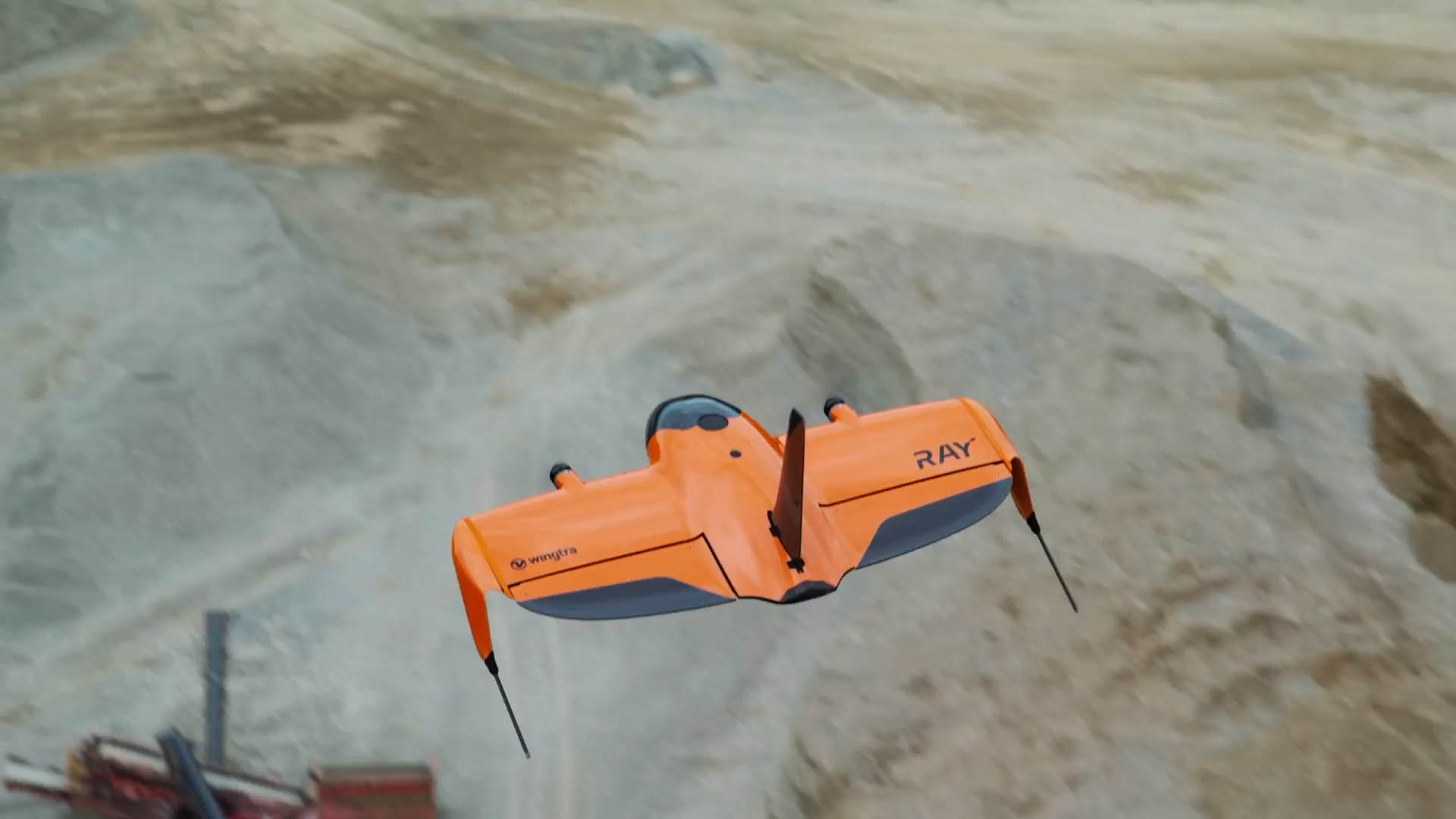
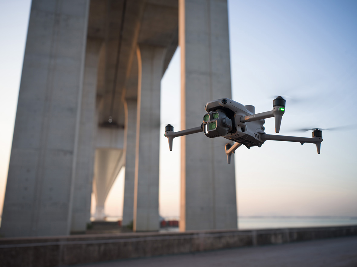
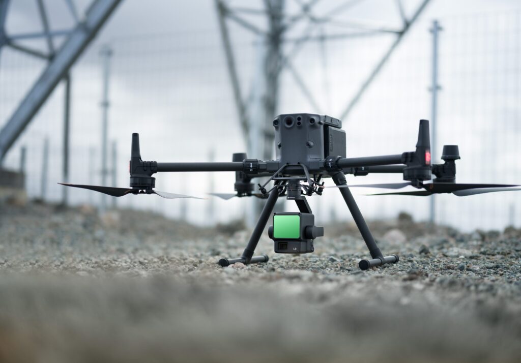
Good 3D mapping begins on the ground. For most 3D mapping applications, a double-grid or crosshatch flight pattern is preferable to a standard single-pass grid, as it captures imagery from multiple angles and improves reconstruction of vertical surfaces. Aim for a frontlap of at least 80 per cent and a sidelap of 70 to 80 per cent, with a GSD of 2 to 5 centimetres for survey-grade work. Camera settings should minimise motion blur: a fast shutter speed, low ISO, and fixed aperture are the baseline. The Zenmuse P1 45-megapixel full-frame sensor with mechanical shutter is a strong choice for photogrammetric work. For large-area surveys, the WingtraRAY offers the endurance and coverage to complete the mission in a single session; the DJI Matrice 4 Series suits smaller or more complex sites, with options for LiDAR payloads such as the Zenmuse L2 or Zenmuse L3 where canopy penetration is needed.
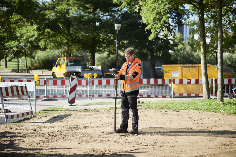
Ground control points (GCPs) are surveyed reference markers that georeference processed data to a known coordinate system and are essential for survey-grade accuracy. A minimum of five, distributed evenly across the site is recommended for most projects. GCPs should be positioned well within the site boundary rather than at the very edges or corners, as markers placed too close to the perimeter may not appear in enough overlapping images to be reliably detected. Some DJI Matrice and Wingtra platforms incorporate onboard RTK receivers that can reduce or eliminate the need for physical GCPs, but independent check points should always be surveyed to verify output accuracy regardless of the positioning method used.
Before importing imagery into processing software, review the dataset: remove any images not captured as part of the planned mission parameters, such as those taken during takeoff, landing, or any unplanned deviations from the flight path, check for motion blur or poor exposure, and confirm that all images are correctly geotagged in the project coordinate system. Mismatches between the image coordinate reference system and the GCP coordinate system are a common source of georeferencing errors and are far easier to resolve at this stage than after processing has begun. Import GCP coordinates as a CSV file and mark each GCP in at least eight to ten images from varied viewing angles to give the software the most robust spatial fix.
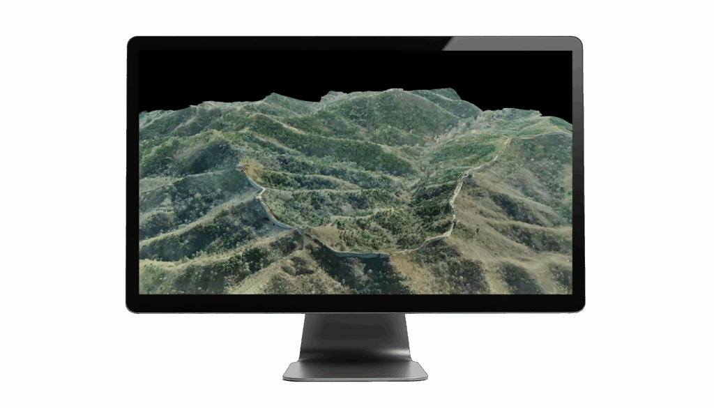
Structure from Motion first identifies common feature points across overlapping images to calculate camera positions and orientations, producing a sparse point cloud. Multi-view stereo (MVS) then uses pixel-level matching to generate a dense point cloud, which is the most computationally demanding step. From the dense cloud, the software builds a textured 3D mesh, a continuous surface mapped with colour from the original imagery. Processing platforms including Pix4Dmapper, Agisoft Metashape, DJI Terra, and WingtraCLOUD each have different strengths in speed, automation, and output formats. For survey-grade deliverables, process at the highest quality setting your hardware can manage within the project timeline.
Once reconstruction is complete, GCPs are applied to align the model to real-world coordinates. Bundle adjustment then refines camera positions, orientations, and GCP locations simultaneously, producing a quality report with RMS error values for each control point. Target RMS values below 5 centimetres are generally acceptable for most survey applications. Independent checkpoints, which are not used in processing, provide an objective measure of absolute accuracy and should be verified before any deliverables are produced. Where real-time correction data is needed in the field, Trimble VRS Now UAV delivers reliable RTK accuracy across the UK network without requiring a local base station. KOREC can advise on the most appropriate positioning approach for your accuracy requirements.
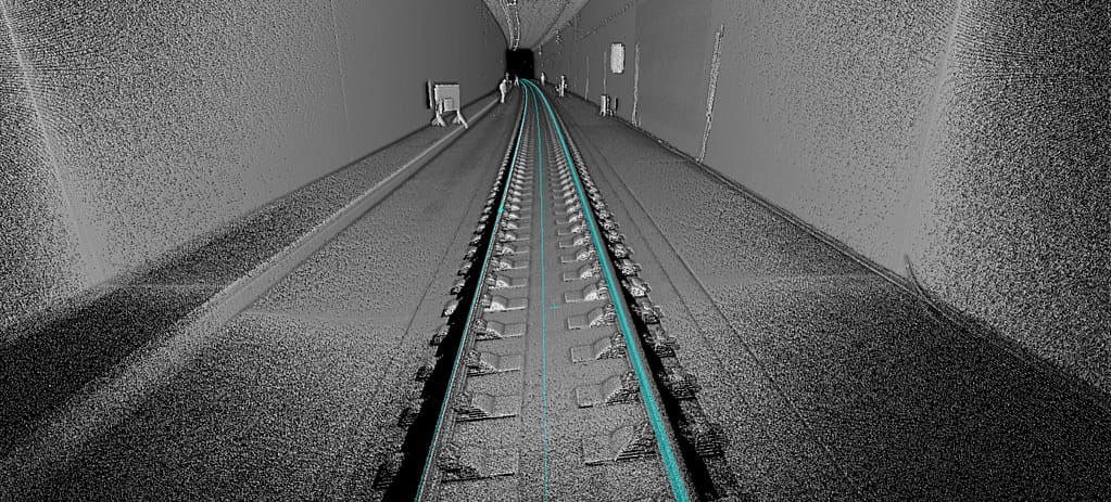
The core outputs from a UAV mapping project are the orthomosaic, DEM, DSM, and point cloud. An orthomosaic is a geometrically corrected aerial image from which accurate measurements can be taken directly, typically exported as a GeoTIFF. A Digital Elevation Model (DEM) represents bare-earth terrain; a Digital Surface Model (DSM) captures everything above it including buildings and vegetation. Both are derived from the point cloud and exported as raster grids. Raw point clouds require classification to separate ground points, vegetation, and noise: for sites with heavy canopy, a LiDAR payload delivers considerably better ground separation than photogrammetry alone. Contour lines derived from the DEM and textured 3D mesh models exported as OBJ or FBX files round out the standard deliverable set for most engineering and construction projects.
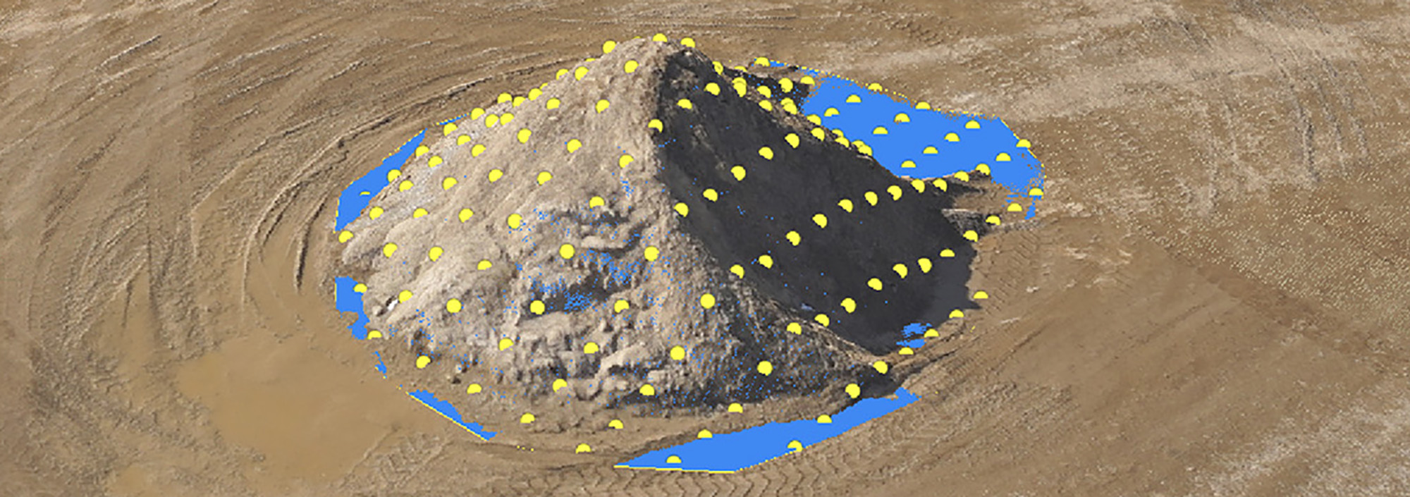
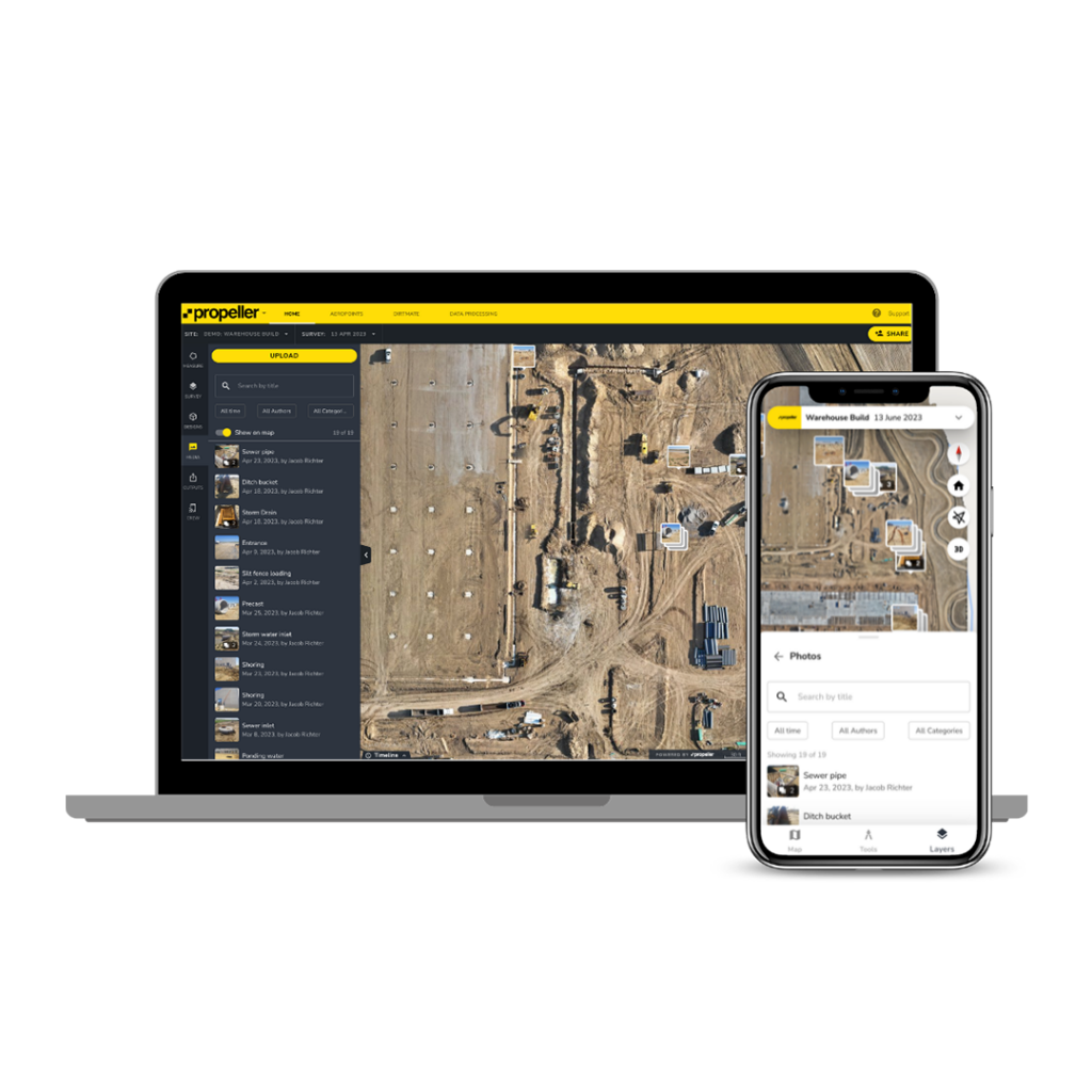
Volumetric measurement is one of the most valuable applications of UAV 3D data. Stockpile volumes, cut and fill quantities, and material movement can all be derived from the point cloud or DSM, with regular repeat flights tracking change over time. A number of platforms used by KOREC customers include built-in measurement tools for this purpose, including Propeller, DJI FlightHub 2, Pix4D, and DJI Terra, each offering volume, area, and distance measurement capabilities directly within their processing or review environments. For construction teams, Trimble Business Center Aerial Photogrammetry integrates drone data processing into the same office environment used for GNSS and total station data. UAV-derived point clouds and mesh models also integrate directly into BIM workflows for as-built documentation. For client delivery, Soarvo, available through KOREC, allows stakeholders to explore 3D datasets, take measurements, and collaborate in a web browser alongside data from total stations, laser scanners, and GIS files, without needing specialist software. Standard deliverable formats include GeoTIFF for orthomosaics and DEMs, LAS or LAZ for point clouds, DXF for CAD outputs, and IFC for BIM integration.
Quality control should run through every stage of the workflow, not just at the end. Review the processing report after each run, checking GCP and checkpoint residuals against your accuracy requirement. Inspect outputs visually for distortions, gaps, and areas of poor reconstruction. The most common issues are doming or bowl-shaped distortions in the DEM, caused by insufficient GCP distribution or over-reliance on onboard GNSS without ground control; and poor reconstruction of vegetated areas, where foliage movement between captures creates inconsistencies. Switching to a LiDAR payload is the most reliable solution in dense vegetation. For repeat survey projects, comparing outputs against a previous baseline is a useful check for any systematic shift in your workflow.
The most productive UAV 3D mapping workflows are built on consistent, standardised habits: fixed file naming conventions, saved processing presets, and quality reporting templates that apply across every project and every operator. Always carry out a pre-flight site assessment covering airspace, obstructions, signal interference, and weather suitability. Review your processing reports after every project: understanding where errors arise and how they relate to field conditions steadily improves the reliability of your outputs over time. The photogrammetry workflow rewards methodical working, and quality control is most valuable when it is treated as integral to every stage rather than as a final check.
KOREC supplies a comprehensive range of drone and UAV systems, payloads, processing software, and correction services, alongside pilot training through trusted CAA-approved partners. Whether you are setting up your first UAV mapping workflow or extending an established capability into new deliverable types, our team is on hand to help. Explore our resources for surveying, mapping and GIS, and construction applications.
KOREC can advise you on the right drone for your project. Speak to our friendly experts today to get the right technology to solve your business challenges.